The basic arrangement we have used for gathering data about fluid flow
and evaporation during spin coating is shown at right. A HeNe laser was
reflected of the center of the spinning silicon wafer. Our typical conditions
have the angle of incidence very close to normal incidence. A photoconductive
device was then used to measure (qualitatively) the intensity of the reflected
light. As the liquid layer thins the laser light goes through successive
interference conditions where either constructive or destructive interference
will occur. If the conductivity of the photoconductive device is monitored
during the entire duration of a spinning run, then the time evolution of
the thickness of the fluid layer can be determined (by working backwards
from the known endpoint of zero thickness).
This second figure shows a typical interference scan for a spinning run
of a sol-gel material on silicon. The early times (0-5 seconds or so) show
very rapid thinning of the fluid -- to the extent that the fringes overlap
and blur (limited by the capture speed and detector response time). Later
in spinning the fringes can be easily counted -- and their spacing gradually
gets wider and wider as the coating thins (and then thins more slowly as
a result). Finally, the intensity tails off after the coating reaches its
final thickness and some residual solvent is slowly extracted from the
gel layer.
Finally, the fringe data can be mapped to the expected thinning function
(described in more detail at the spinning basics/flow
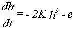
analysis page). As described there, the expected thinning rate (dh/dt)
will follow this expression:
where "K" and "e" are the applicable flow and evaporation
constants, respectively. Thus, the figure at right shows a plot of -dh/dt
versus 2*h-cubed, yielding a line where the slope gives "K" and the intercept
gives "e". Then, for well behaved systems, the applicable viscosity and
evaporation rate can be determined.
Experimental
tests and validation of this procedure for pure solvents can be found in
this reference:
D. P. Birnie, III and Manuel Manley, "Combined Flow and Evaporation
of Fluid on a Spinning Disk", Physics of Fluids, 9, 870-875 (1997).
This experimental
technique has also now been tested on mixed solvent systems and on sol-gel
solutions (click here to view).
Page last edited February 2005.
(c) 1998, 2005 Dunbar
P. Birnie, III
 The basic arrangement we have used for gathering data about fluid flow
and evaporation during spin coating is shown at right. A HeNe laser was
reflected of the center of the spinning silicon wafer. Our typical conditions
have the angle of incidence very close to normal incidence. A photoconductive
device was then used to measure (qualitatively) the intensity of the reflected
light. As the liquid layer thins the laser light goes through successive
interference conditions where either constructive or destructive interference
will occur. If the conductivity of the photoconductive device is monitored
during the entire duration of a spinning run, then the time evolution of
the thickness of the fluid layer can be determined (by working backwards
from the known endpoint of zero thickness).
The basic arrangement we have used for gathering data about fluid flow
and evaporation during spin coating is shown at right. A HeNe laser was
reflected of the center of the spinning silicon wafer. Our typical conditions
have the angle of incidence very close to normal incidence. A photoconductive
device was then used to measure (qualitatively) the intensity of the reflected
light. As the liquid layer thins the laser light goes through successive
interference conditions where either constructive or destructive interference
will occur. If the conductivity of the photoconductive device is monitored
during the entire duration of a spinning run, then the time evolution of
the thickness of the fluid layer can be determined (by working backwards
from the known endpoint of zero thickness).
 This second figure shows a typical interference scan for a spinning run
of a sol-gel material on silicon. The early times (0-5 seconds or so) show
very rapid thinning of the fluid -- to the extent that the fringes overlap
and blur (limited by the capture speed and detector response time). Later
in spinning the fringes can be easily counted -- and their spacing gradually
gets wider and wider as the coating thins (and then thins more slowly as
a result). Finally, the intensity tails off after the coating reaches its
final thickness and some residual solvent is slowly extracted from the
gel layer.
This second figure shows a typical interference scan for a spinning run
of a sol-gel material on silicon. The early times (0-5 seconds or so) show
very rapid thinning of the fluid -- to the extent that the fringes overlap
and blur (limited by the capture speed and detector response time). Later
in spinning the fringes can be easily counted -- and their spacing gradually
gets wider and wider as the coating thins (and then thins more slowly as
a result). Finally, the intensity tails off after the coating reaches its
final thickness and some residual solvent is slowly extracted from the
gel layer.
 Finally, the fringe data can be mapped to the expected thinning function
(described in more detail at the
Finally, the fringe data can be mapped to the expected thinning function
(described in more detail at the